Saturday, October 18, 2014

2-Wire Interface

2-Wire Interface, popularly known as I2C is one of the methods used to communicate with other hardware, like a sensor or any other controller on the board, which supports I2C. As most of us know and as the title hints, I2C needs only 2 lines/wires to communicate. SDA(data line) and SCL(clock line). The speed of I2C communication(bit rate) depends on devices, ranged from 100-kHz till 5-MHz.

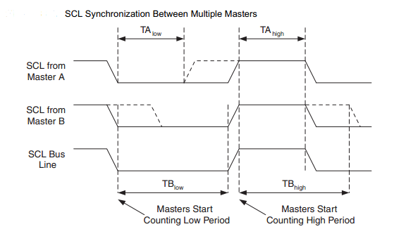
All I2C devices are 7 bit addressable. That means, maximum of 128 devices can be connected to those SDA and SCL lines (I2C bus). I2C devices can be connected to I2C bus in 4 mode of communication: Master Transmit, Master Receive, Slave Transmit and Slave Receive. Any device connected to I2C bus, can be a master (that means taking control of that bus), rest of the connected devices will become slaves. When more more than one device tries to take control of the I2C bus, bus arbitration decides which device will be master. When multiple devices are trying to become master, SCL line of I2C bus is High, when all connected master's SCL is High and is Low when all connected master's SCL is Low.

If master wants to broadcast data to all the connected I2C devices, then master has to use the address 0x00, which is known as general call. When master wants to communicate to one particular device, then master has to use that device's address. Once Slave has been addressed by any master, it will either sends the data or receives the data from the master. Slave will always have the freedom to hold the SCL line until interrupt has been served, which is known as clock stretching. Once the I2C communication started, it's master's responsibility to stop the I2C communication. Master has the freedom to do a repeated start without freeing the I2C bus.

I2C specifications are:
+ Start condition - SDA line transition from High to Low when clock is high.
+ Stop condition - SDA line transition from Low to High when clock is high.
+ Data will be of 9 bits length. 8 bits of address or data, and one bit is for acknowledgement for byte reception.
+ When master transmit slave's address. It has to send the slave's 7 bit address from bits 7:1 and 0th bit will Read/Write bit (1- read, 0 for write).

Steps for writing I2C communication code:

  1. Go through the I2C or Two Wire Interface(TWI) part of datasheet (click here for Atmega644P).
  2. Assign the self address for device.
  3. Initialize the bit rate register based on the speed in which communication has to happen.
  4. Enable the I2C communication, Enable the interrupt, Enable the acknowledgement.
  5. If Device has to be configured as Master, then set the Start Condition bit. (In some controllers, you can start the communication by setting the Start Condition bit and Interrupt flag reset bit).
  6. Write a ISR, for interrupt handling. In ISR, monitor Status register, and based on the value in the status register, take an appropriate action and reset the interrupt flag.
  7. In master mode, when there is a interrupt for successful transmission of start condition, slave's address has to be updated in the data register (7:1 bit) and 0th bit indicating the direction of transfer (1 for read and 0 for write).
  8. When Device wants to receive or transmit more than one byte of data, a buffer has to be maintained. For transmitting data, buffer has to filled before(in master transmit) and/or during the communication (in slave transmit).
  9. When configured as slave mode, device has to wait until the direction is know. like:

Note: Disabling the acknowledgement in slave mode is one of the way for device to avoid all I2C communication.

Click here for I2C driver code for Atmega644P. With that, any I2C device with known address can be connected and communicated. The demo of I2C driver testing can be found in below links:

Friday, December 13, 2013

Redefining printf() and scanf() !

If you are a C programmer then you are very-much familiar with printf() and scanf(). Many a times we use printf() to debug. For embedded guys printf() is like a OASIS when there is no debugging tools available! But most of the compilers for micro-controllers will not have printf() and scanf() builtin!. So many embedded developers like to port printf() and scanf(). Some will succeed, some will struggle a lot and some will fail. Here I will try to explain how we can re-define printf() and scanf().

printf() and scanf() are just functional calls like other functional calls that we define and/or use in our programs. Only difference between these 2 functions and other functions we use/define is, NUMBER OF ARGUMENTS passed to the function. For printf() and scanf() it is unknown. In C, we have very nice concept (/module we can say) which is very much less used (reason could be because it eats up stack!) in C programming. It is VA-ARG. This handles the variable number of arguments passed to the function. All most all the compilers out there (for AVR or ARM or PIC) will have stdarg.h header file in library, which will have the macros va_start, va_arg, va_end, va_copy, and va_list data type. All we need to do while defining our own version of printf() and scanf() are, use ellipsis ("...") as one of the arguments, and use va_start, va_arg and va_end macros when we need it.

This is how I re-defined my version of printf() and scanf() - click here for code:

  • I have used print() for printf() and scan() for scanf().
  • I had usart/uart driver and hookups for transmit and receive data using serial communication (you can check my previous post or code).
  • I have defined only for reading/writing integers, hex numbers, characters and strings! (this can be modified to serve your purpose!).
  • Max range of Integers that my functions can handle is -2147483648 to 2147483647! and in Hex is 0x00 to 0xFFFFFFFF. (Code can be modified for 64 bit, different range of integers and for long ints - %ld etc.)
  • In my code, I can read maximum of 200 bytes! because I have allocated only 200 bytes as buffer length. So when I want to read any string I should make sure that I have to allocate the memory less than 200 bytes! When multiple data are read I have to make sure that it will not exceed more than 200 bytes or I can read multiple data with more than one scan() functional call! (or you can increase the buffer length). And I have used ENTER KEY as the end of data inputs (you can modify in such a way that '!' or any special character as the indicator for end of data inputs).
  • When I worked with AVR and ARM controllers I have observed that, ENTER KEY from keyboard is considered as CARRIAGE RETURN (ASCII value 0x0D). Where as, in GCC compilers ENTER KEY  is considered as just a NEW LINE (ASCII value 0x0A) (You can see usage of both in my code!).
  • I have used putty to see the things on my laptop screen and connected to Sanguino board with USART/UART. When I used '\n' in print() I thought courser will point to the beginning of new line, instead courser in new line was placed where previously printed line was ended! So when I used '\r' after '\n' courser was pointing to the beginning of new line.
  • While printing single character with "%c", in va_arg I have given type as int not char. Char is not allowed in va_arg. Check the print() definition in code.
  • main() (commented part of the code at the end) in printf_code.c and scanf_code.c files is to test my function definitions using MinGW GCC compiler. When I used printf_code.c and scanf_code.c files for my Sanguino board, I have adjusted with data types and other things for AVR compiler.

Friday, November 15, 2013

UART Communication - Atmega644p

U(S)ART is Universal (Synchronous) Asynchronous Receiver and Transmitter. It is the simplest form of communication used to communicate with any micro-controller either for debugging or for data transfer or for flashing! First thing we should know before using USART/UART communication is baud-rate. Baud-rate is the number of bits transferred per second. ex: 9600 i.e. 9600 bits transferred per second.

Micro-controllers needs Voltage source and Clock to run. Clock is like heart beat for any micro-controller. Clock is the word given for oscillations produced by the crystal oscillator. Oscillations produced by crystal oscillator is measured in terms of Hz. ex: 8 MHz - i.e. 8 * 10^6 oscillations per second. At every oscillation micro-controller can execute an instruction.

To establish USART communication, If baud rate is b, then b number of bits has to transferred in f number of oscillation (where, f is clock speed or number of oscillations in 1 sec). So, 1 bit should be transferred after every f / b oscillations (let, x = f / b). After every x oscillations 1 bit has to be transferred to reach a baud rate of b. We can have counter to monitor these x oscillation. Counters will increment or decrements after every oscillation. For up counter one extra clock cycle/oscillation is required, as count value needs to be loaded to counter after resetting to 0. For down counter one less clock cycle is required as once it resets it can directly reloaded with count value. Counter initialization, increment or decrements of count is nothing but execution of instructions. Let us say d (divider) is the clock cycles required to execute those instructions. Then, new counter value will be x = ( (f / b) / d ).
For Up counter x = (f / (b * d)) + 1,
for Down counter x = (f / (b * d)) - 1.

Each micro-controller will have the following registers:

  • Baud Rate Register (Counter value)
  • Data Register(s) - for Transmitting/Receiving the data
  • Configuration Registers

USART/UART configuration like Number of data bits, number of stop bits, parity bits, synchronous or asynchronous, interrupt driven, receive or transmit can be done by writing appropriate bits in Configuration Registers. Data Register(s) empty or filled information, communication error information, interrupt flag information can also be found in Configuration Registers.

Steps for writing USART/UART communication code:

  1. Go through the USART/UART part of datasheet for micro-controller (click here for Atmega644p).
  2. Initialize the Baud Rate Register (counter value calculated using the above formula. Check datasheet to verify the formula, also check the baud rate error range).
  3. Configure the USART/UART by setting appropriate bits in Configuration Registers
  4. For receiving data, wait for data to be available in Data Register and then return the Data Register content. pseudo code: 
  5. For Transmitting data, wait for Data Register to become empty and then fill the Data Register with the data to be transmitted. pseudo code: 

Click here for USART driver code files for Atmega644p (Sanguino). With that you can easily communicate with your Atmega644p (Sanguino board).

Note: Board used for testing the code is Sanguino which has Atmega644p chipset.

Thursday, July 25, 2013

Bare-Metal Programming - Sanguino!

For people who might not be knowing what is Bare-Metal programming is, I just want to brief about it. It is low level programming!. By default when we install the SDK, IDE and when we add libraries (downloaded from web) for our project, usually for all drivers including the pin configuration(GPIO), USRAT/UART, SPI or I2C etc will have the APIs to configure, writing or reading the data. While writing code for our project, as a developer we will try to use those APIs and write programs. Bare-Metal programming involves either creating our own APIs (for future use) or using the direct registers while writing program for our project.

People who bought Sanguino / Arduino development boards for practice or for hobby will get the Arduino software, FTDI driver and IDE in a CD. Programming using that IDE is not the usual C programming as we know of, it is a derived from C, and language is called Processing programming language. Some developers would like to use the open source IDEs with normal C coding. For such developers I would like to share my thoughts and steps involved in doing so.

Note: I have used the CodeBlock as the IDE and checked with Sanguino board(ATmega644p controller). This should be the same procedure for any Arduino and AVR controller boards (I have not tested for all Arduino or AVR controller boards, tested only on ATmega644p Sanguino board).

Step 1: Make sure that you have open source IDE or IDE which you are familiar with and you can change the compiler settings for build (in my case I used CodeBlock).

Step 2: Download the AVR GCC Compiler (basically these copilers will have the registers, SFR pages etc.. required for AVR controllers) and install the AVR GCC compiler.

Step 3: Now we have to setup the IDE for AVR controllers. For CodeBlock IDE, in settings, click on the compiler, in that under select compiler select "GNU AVR GCC Compilers", under compiler settings tag, for compiler flags, check the ATmega644P. Under Toolchain executables, Give your directory path where you have installed the AVR GCC Compiler, for C compiler mention the name of the exe file like below:
You can also select the optimization level, and many other settings which suits your requirement!

Step 4: Create the project, and make sure that for that project both Debug and Release builds are having the same Compiler settings. And now just give build with empty main.c file! If build goes through without any error, then compiler settings are fine. You are ready to implement your project!
Click here, for the example project! which will toggle LED connected to PortB, pin 0.

Note: In the latest version of the code::blocks and AVR compiler toolchain, the linker will be pointing to wrong libc.a static library. Which might not be needed for your project to build and execute. If linking libc.a is not required, please make sure to delete the <path to AVR compiler>\avr\lib in Settings -> Compiler -> Search directory Tab -> Linker Tab

Step 5: Now, once the code is ready with binaries (.hex files) we need to flash (download) that to our controller board. that can be done with avrdude or some app which will help in programming our controlled board. One such app is XLoader. With that you have to give the path for the .hex file, com part number and baud-rate at which your controller needs to be flashed. For ATmega644P the baud-rate for flashing serially is 38400. (Make sure that when your controller board is connected with the help of USB cable com port connection is established. If needed install FTDI drivers)

Once controller board is flashed, your program should be working. If it is simple LED blinking program attached above, you can verify that by LED toggling. With this example you have successfully written bare-metal programming! Now you can write code for your project in C with direct register access and with IDE of your own choice! :)